In this post, I go over how to generate a 1Hz clock source through an unusual way.
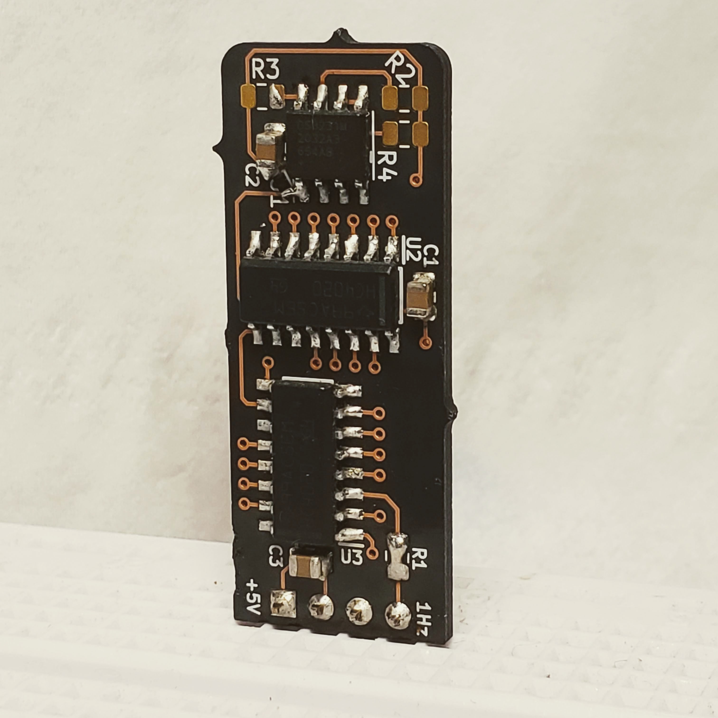
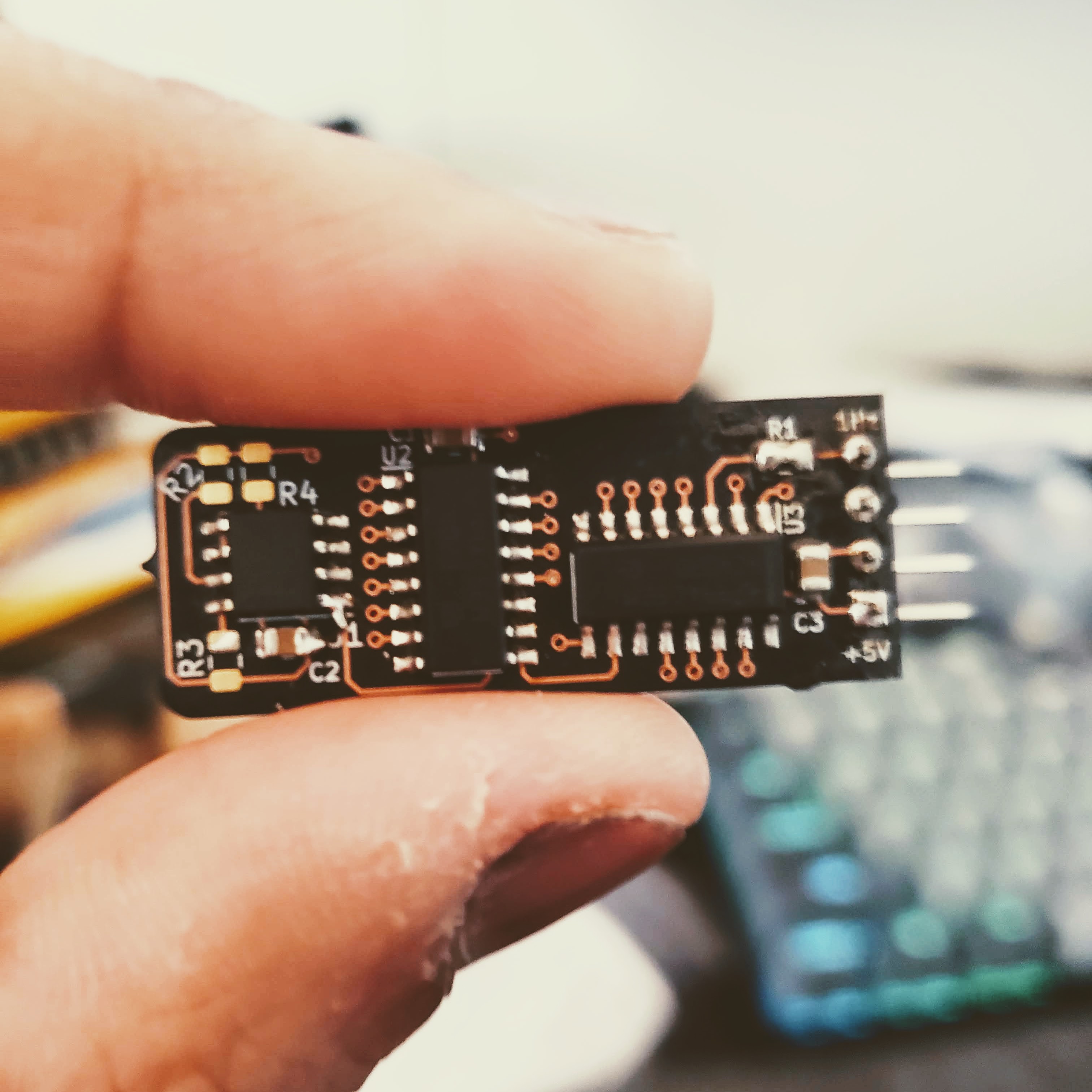
PCB close up
Parts needed
| Part number | Quantity |
|---|---|
| DS3231M | 1 |
| 74HC4020 | 2 |
| 1uF, 0603 | 3 |
| 4.7k, 0603 | 1 |
I have been looking for an accurate clock source for another project (that I will be publishing here soon). The more accurate an oscillator or crystal is, the more expensive it becomes. The easiest way to generate a 1Hz clock source is to generate or use a 32.768 kHz source. It’s a common frequency available and it cleanly divides down to 1Hz.
During my search for accurate 32.768 kHz TCXOs, I found one from Maxim IC. It was their popular DS32xx family of RTC ICs and they specifically made a TCXO version only. From there, I found these two parts: DS3231 and DS3232M. They are RTC chips but also have a dedicated 32.768 kHz output. Two main differences between them is that the DS3231M runs off +2.3 to +5.5 volts and requires a pullup on the 32.768 kHz output.
Now, obviously, using a dedicated a 32.768 kHz TCXO would be the best way to go, but where is the fun in that? I wanted to see if I could use this RTC chip as a standalone 1Hz source (spoiler alert: you can, but with some caveats).
DS3231M / DS3232M
Both the DS3231M and DS3232M have a dedicated 32.768 kHz output pin. The only difference being that the DS3231M requires an external pull up resistor (4.7k should suffice). From here on out, I will only be referring to the DS3231M.
You’re probably wondering why would I go thru all this trouble to use a RTC chip that has an I2C interface just to create 32.768 kHz clock source. The details in the datasheet will help answer this question.
The most important question is what steps are needed to actually use the 32.768 kHz output pin. The answer is, it just needs to be powered on from VCC, not the battery. That’s it. Let’s take a closer look.
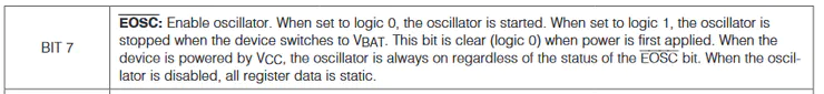
Here is the pin description:

When enabled with the EN32KHZ bit in the status register, it works on either power supply (VCC or battery).
This bit enables and disables the 32kHz output. A logic ‘1’ means it’s active. On initial power up, it’s set to a logic ‘1’ but only if the oscillator is enabled.

The enable oscillator bit is active when set to logic ‘0’ and disabled when set to logic ‘1’. This bit is set to a logic ‘0’ on power up AND the oscillator is always on regardless of this bit if the device is powered by VCC.
What all this means is that as long as the pull up resistor is present and the device is powered on by VCC, the 32.786 kHz clock source will be present on that output pin.
74HC4020
Next is to figure out how many times do we have to divide by 2 to get to 1Hz from 32,768 Hz.

15 times is what it takes to get down to 1Hz.
The SN 74HC4020 is a 14 bit binary ripple counter. Ripple means that the output of the first flip flop in the stage is the input of the 2nd state and so and so forth. The output of each flip flop (except the 2nd and 3rd) are brought out to be as outputs.
The SN 74HC4020 is a 14 bit binary ripple counter. Ripple means that the output of the first flip flop in the stage is the input of the 2nd state and so and so forth.
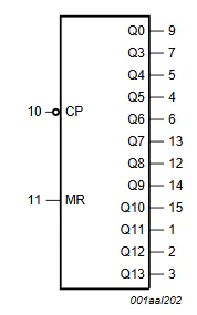
One of these will get you down to 2 Hz. So, there are two ways to go about it. You can either have a 2nd one of these ICs, feed the 2 Hz into the CP pin and Q0 to get the 1Hz or use a flip flop to do a divide by 2.
I decided to use the first 4020 IC to divide the 32.768 kHz to 16.384 kHz. The second 4020 was used to divide all the down to 1 Hz. The schematic and layout are shown below.
Testing
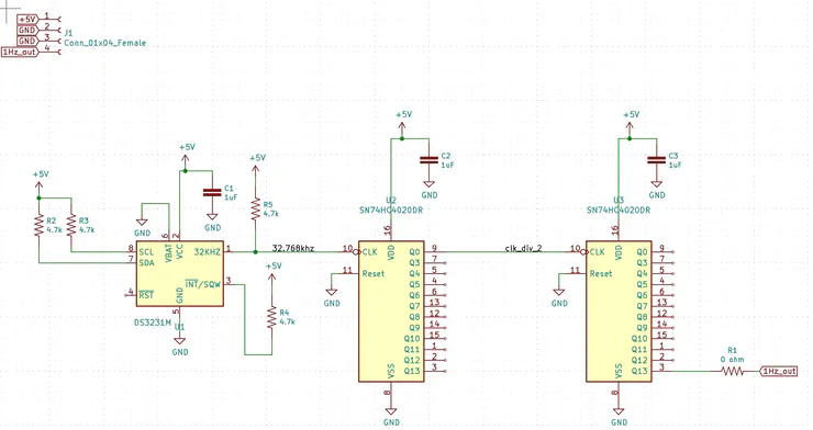
Schematic
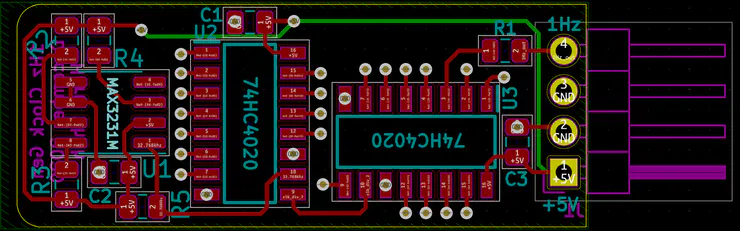
Layout
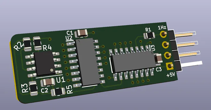
3D View
Here is what the assembled PCB looks like. I forgot to put in a place for the pull up resistor, but installed it in there during soldering. It’s a pretty tiny board! This was done with the Oshpark after dark service.
My scope does not show enough significant digits on the measurement. If you decide to build it and have access to a more accurate measurement device, please drop a comment with a screen capture.
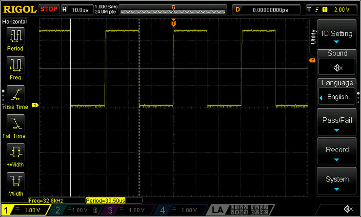
32.768 kHz
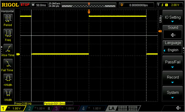
2Hz Out
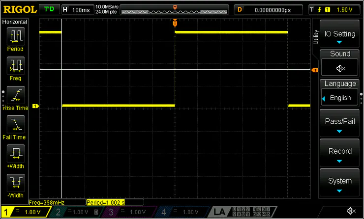
1Hz_out
Stay tuned for the project I made this for. That should do it! Thanks for reading!