In the second part, I will be going over how to link up data captured from an MQTT server published to a Node Red server with Google sheets for that sweet data!
Parts Used
| Part number | Quantity |
|---|---|
| Wemos D1 Mini | 1 |
| BME280 | 1 |
| Breadboard | 1 |
| Jumper wires | 4 |
1) Temperature Logging Hardware Setup
Now that the MQTT and node-red servers are setup and configured from part 1, let’s build a data collecting test circuit. For this example, I will be using a BME280 temperature/humidity/pressure sensor. More information about the IC can be found here.
To communicate with it, I will be using a Wemos D1 Mini, based on the ESP8266 WiFi enabled micro-controller. There are 2 prerequisites to use this hardware setup.
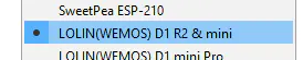
1) Make sure the Arduino IDE is setup to use the Wemos D1 Mini board. Under the board manager in Arduino IDE, select this board:
2) I wrote a BME280 Arduino library that can be found on my GitHub here: https://github.com/hshah89/BME280_Arduino_Driver
Download and copy the drivers to the appropriate Arduino library folder for your operating system.
Windows:
    C:\Users\<username>\Documents\Arduino\libraries
MacOS:
    /Users/<username>/Documents/Arduino/libraries/
Once you have the above configured, proceed to wiring up the sensor board to the micro-controller board using the schematic below:

2) Temperature Logging Software
With the hardware wired up per the schematic above, it’s time to program the micro-controller and verify the sensor is printing out data. Copy and paste the code into a new Arduino project.
Update these two lines with your WiFi information. If you don’t have a separate 2.4GHz and 5GHz network, your router is most likely broadcasting both under the same SSID. In that case, just enter that SSID and its password in the quotes. Please keep in mind that the ESP8266 only supports 2.4GHz WiFi networks.
char _SSID[] = "<2.4GHz WiFi SSID>";
char _PSWD[] = "<2.4GHz WiFi SSID password>";
Then replace the lines in the code below under the “// WiFi/MQTT Config” comment.
// I N C L U D E S
//-------------------------------------------------------------------------------------
#include <ESP8266WiFi.h>
#include <Wire.h>
#include "bme280.h"

// D E F I N E S
//-------------------------------------------------------------------------------------
#define BAUD_RATE     115200
#define dev_addr      0x76

// G L O B A L  V A R I A B L E S
//-------------------------------------------------------------------------------------
// WiFi/MQTT Config
char _SSID[] = "<2.4GHz WiFi SSID>";
char _PSWD[] = "<2.4GHz WiFi SSID password>";
const char* device_name = "Master Bedroom";

// BME280 variables
float pressure;               // Storing measured pressure reading
float temperature;            // Storing measured temperature reading
float humidity;               // Storing measured humidity reading

uint8_t chip_id;              // Storing BME280 Chip ID

char _temp_[10];
char _humid_[10];
char _pressure_[10];

BME280 sensor_bme280;

// S E T U P
//-------------------------------------------------------------------------------------
void setup() {
  Wire.begin();
  Serial.begin(BAUD_RATE);

  _wifi_setup();

  sensor_bme280.settings.i2c_addr = dev_addr;           // Set the device i2c address

  Serial.println("BME280 - Temperature, Humidity, and Pressure Sensor\n");
  Serial.print("Chip ID = 0x");
  Serial.print(sensor_bme280.begin_i2c(), HEX);
  Serial.println("\n");

  sensor_bme280.set_humid_osrs(bme280_osrs_two);
  sensor_bme280.set_temp_osrs(bme280_osrs_two);
  sensor_bme280.set_pres_osrs(bme280_osrs_two);
  sensor_bme280.set_mode(bme280_forced_mode);

  Serial.println("Settings");
  Serial.println("----------------------------------------------\r");
  Serial.print("CTRL HUM\t0x");
  Serial.print(sensor_bme280.read_reg(bme280_ctrl_hum_addr), HEX);
  Serial.print("\nCTRL MEAS\t0x");
  Serial.print(sensor_bme280.read_reg(bme280_ctrl_meas_addr), HEX);

  temperature = sensor_bme280.read_float_temp_f();
  pressure = sensor_bme280.read_float_pres();
  humidity = sensor_bme280.read_float_humidity();

  Serial.println("\n\nTemp\t\tHumidity\tPressure");
  Serial.println("----------------------------------------------\r");
  getData();
}

// L O O P
//-------------------------------------------------------------------------------------
void loop()
{
  delay(10e3);
  getData();
}

// F U N C T I O N S
//-------------------------------------------------------------------------------------
void getData()
{
  sensor_bme280.set_mode(bme280_forced_mode);
  temperature = sensor_bme280.read_float_temp_f();
  pressure = sensor_bme280.read_float_pres();
  humidity = sensor_bme280.read_float_humidity();
  Serial.print(temperature);
  Serial.print(" ºF \t");
  Serial.print(humidity);
  Serial.print(" % \t");
  Serial.print(pressure);
  Serial.print(" hPa \t\n");
}

void _wifi_setup(void) {
  Serial.print("\nWiFi Connecting");
  WiFi.hostname(device_name);
  WiFi.begin(_SSID, _PSWD);

  while ( WiFi.status() != WL_CONNECTED ) {
    delay(200);
    Serial.print(".");
  }

  Serial.print("\nWiFi Connected\n");
  Serial.print(WiFi.SSID());
  Serial.print("\t");
  Serial.print(WiFi.localIP());
  Serial.print("\n\n");
}
Once the code is saved, compile and upload the code. If all goes well, open up the serial monitor with a baudrate of 115200 and you should see an output similar to this:
22:06:13.236 -> WiFi Connecting......................................................
22:06:25.525 -> WiFi Connected
22:06:25.525 -> AWE-some-sloth	192.168.1.186
22:06:25.525 ->
22:06:25.525 -> BME280 - Temperature, Humidity, and Pressure Sensor
22:06:25.572 ->
22:06:25.572 -> Chip ID = 0x60
22:06:25.572 ->
22:06:25.572 -> Settings
22:06:25.572 -> ----------------------------------------------
22:06:25.572 -> CTRL HUM	0x2
22:06:25.572 -> CTRL MEAS	0x49
22:06:25.572 ->
22:06:25.572 -> Temp		Humidity	Pressure
22:06:25.572 -> ----------------------------------------------
22:06:25.572 -> 76.40 ºF 	27.90 % 	1018.12 hPa
22:06:35.545 -> 76.36 ºF 	26.85 % 	1018.09 hPa
22:06:45.576 -> 76.35 ºF 	27.09 % 	1018.11 hPa
The sensor reading should be updating every 5 seconds.
If you run into any issues, please leave a comment below with the error and I’ll do my best to help fix it.
Now on to the fun part! It took some work to get here, but it’ll be worth it.
3) Node Red and Google Sheets Linking
Using the Library Manager in the Arduino IDE, install the following library:
PubSubClient by Nick O'Leary

This will allow communicating with the MQTT server we created in Part 1.
Next, we will modifying the code from above to allow publishing to the MQTT server.
Update the includes section to include:
#include <WiFiClient.h>
#include <PubSubClient.h>
Add in a variable for the MQTT server ip address:
char mqtt_server[] = "<mqtt_server_ip_address";
Create a WiFiClient and PubSubClient:
WiFiClient BedroomSensor;
PubSubClient client(BedroomSensor);
It can be named whatever you want. I am using “Bedroom Sensor”. The PubSubClient is based off the WiFiClient name.
Next, we add a function to reconnect to the MQTT server if it’s not connected:
void reconnect() {
  while (!client.connected()) {
    if (client.connect("MasterBedrom")) {
      Serial.println("MQTT Connected");
      client.subscribe("MasterBedroom/Temperature");
      client.subscribe("MasterBedroom/Humidity");
      client.subscribe("MasterBedroom/Pressure");
    }
  }
}
Then we update the getData() function to publish the sensor readings.
void getData()
{
  sensor_bme280.set_mode(bme280_forced_mode);

  temperature = sensor_bme280.read_float_temp_f();
  pressure = sensor_bme280.read_float_pres();
  humidity = sensor_bme280.read_float_humidity();

  dtostrf(temperature, 4, 1, _temp_);
  dtostrf(humdity, 4, 1, _humid_);
  dtostrf(pressure, 4, 1, _pressure_);

  client.publish("MasterBedroom/Temperature", _temp_);
  delay(100);
  client.publish("MasterBedroom/Humidity", _humid_);
  delay(100);
  client.publish("MasterBedroom/Pressure", _pressure_);
  delay(100);

  Serial.print(temperature);
  Serial.print(" ºF \t");
  Serial.print(humidity);
  Serial.print(" % \t");
  Serial.print(pressure);
  Serial.print(" hPa \t\n");
}
Finally, we need to connect to the MQTT server on startup. Add the following two lines to the setup() function. I place them right below the _wifi_setup() function so it’s ready before talking to the sensor.
client.setServer(mqtt_server, 1883);
reconnect();
The full code is available at the end of the article.
Now we will verify that the data from the micro-controller is being published via the MQTT server to the Node-Red server. The video below shows how to check if it’s working properly. The debug block is very useful in seeing published data. If things are configured correctly, you’ll see 3 items published every 10 seconds.
Now that we have have working link between the sensor and Node-Red, it’s time to publish to Google Sheets.
The secret ingredient if you will, is Google Forms. Make a new form under your google account with the following questions:
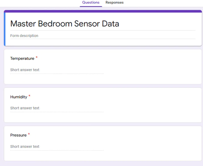
All three fields should be “short answer text” and required. After that, click on the 3 dots on the top right corner and select “Get pre-filled link”.

You’ll see this page:
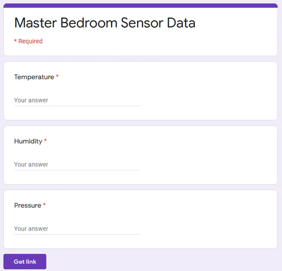
Fill in dummy data for the three fields and then press “Get link”:
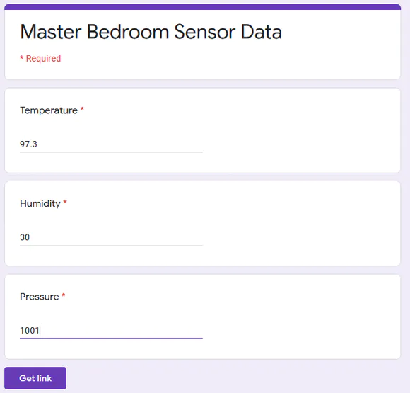
Copy the link, open up notepad (or notepad++) and paste it in there:
https://docs.google.com/forms/d/e/1FAIpQLSdPg9tLqITqlvg8Gfgd9xisgHvTfyPVJbBirfySXSbCvh4Fnw/viewform?usp=pp_url&entry.1828283323=97.3&entry.1066556616=30&entry.320824703=1001
Here are three sections we care about:
* entry.1828283323=97.3
* entry.1066556616=30
* entry.320824703=1001
We replace the dummy data with the following:
* entry.1828283323=
* entry.1066556616=
* entry.320824703=
Finally, replace
/viewform?usp=pp_url&
with
/formResponse?
Now our link to the form looks like this:
https://docs.google.com/forms/d/e/1FAIpQLSdPg9tLqITqlvg8Gfgd9xisgHvTfyPVJbBirfySXSbCvh4Fnw/formResponse?entry.1828283323=&entry.1066556616=&entry.320824703=
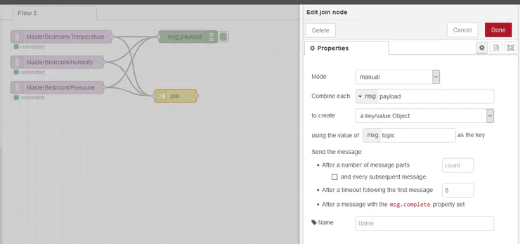
In Node-Red, add a “join” block to combine the message payload from the three readings as shown below:
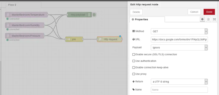
Add a “http-request” block and paste the link from above in the URL:
Hit “Deploy” once done.
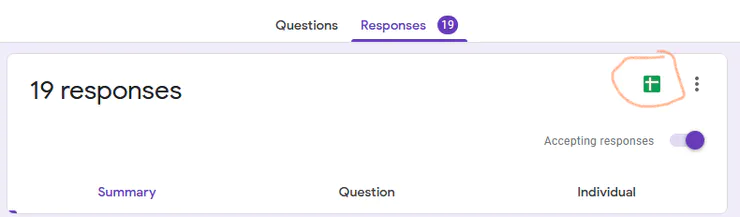
When you go back to the Google Form and click on “Responses”, you’ll see them being updated in real time. See the video of it in action:
So, after all this. How do you get this data to Google Sheets? Click on that circled icon to create a google sheets based on the Google Form data:
The spreadsheet will update every time the form is updated. Here is a video of the whole project in action. Note the drastic rise in temperature data is me blowing hot air on the sensor to show the data is not being faked.
That should do it! If you have any questions, run into an issue, or see where this can be improved/optimized, please leave a comment below. Thanks for reading!