This is a continuation of the 7400 Logic Series clock post. During the build process, there were a few things that didn’t work and a couple of improvements I wanted to add.
Fixes / Updates
| No | Fix/Update |
|---|---|
| 1 | Hour counter |
| 2 | Hour and Minute time set |
1) Hour Counter
I did run into a problem with the hour counter, that was easily fixable. Here is the section:
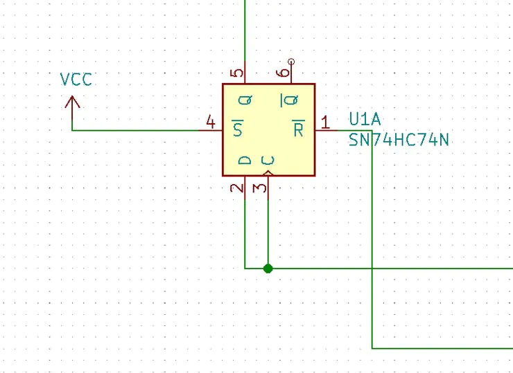
The ripple counter from the ONES part of the hour counter is tied to the D and C pin (input, clock) of the TENS part of the hour counter. Below is the truth table for the flip flop:
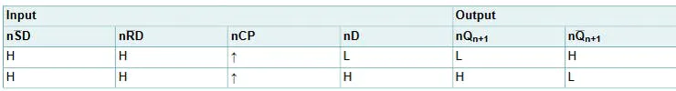
The SET (nSD) pin is set to H. The RESET (nRD) pin gets toggled from H to L when the hour counter goes from 12 back to 1. Otherwise it stays at H. So when the flip flop sees the rising edge of the clock, the D pin is also a rising edge. This essentially results in the output not toggling.
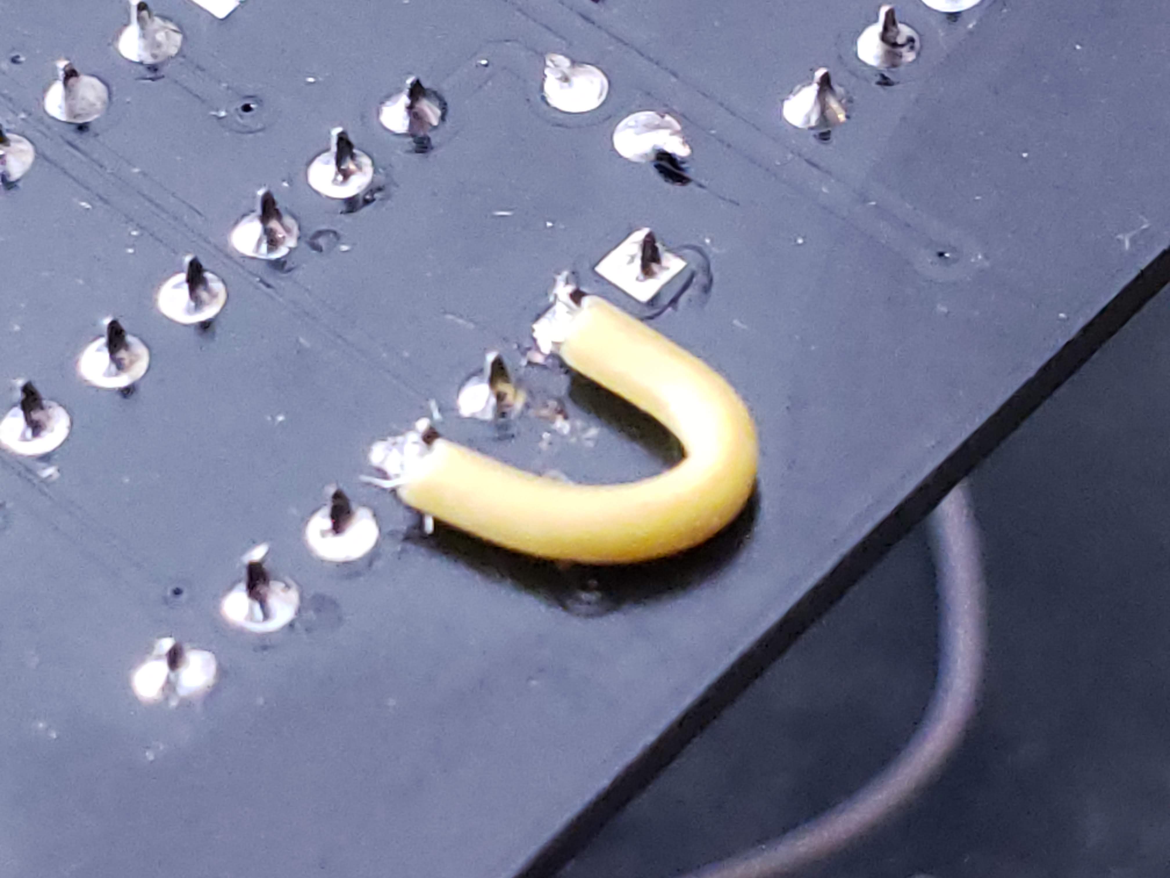
This was resolved by cutting the D pin from the C pin and connecting the D pin to VCC.
So just 1 cut and 1 jumper and the clock worked as designed. See the GIF below:
2) Hour & Minute Time Set
The original method of setting the time did not work. Just an OR gate is not enough. When the switch is pressed, the signal is bouncing are so much that there is no controlled step in count.
Here is the update to the control:
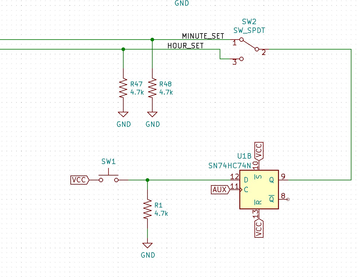
I added 2 switches: 1x push button, 1x slide switch. The slide switch (SW2) selects between the HOUR or MINUTE. The push button (SW1) is used for setting the HOUR or MINUTE. The button output is clocked on the AUX clock coming from the 1Hz source. From the 1Hz source board, I brought out a 1.024 kHz output as the AUX source. This will used to clock the push button.
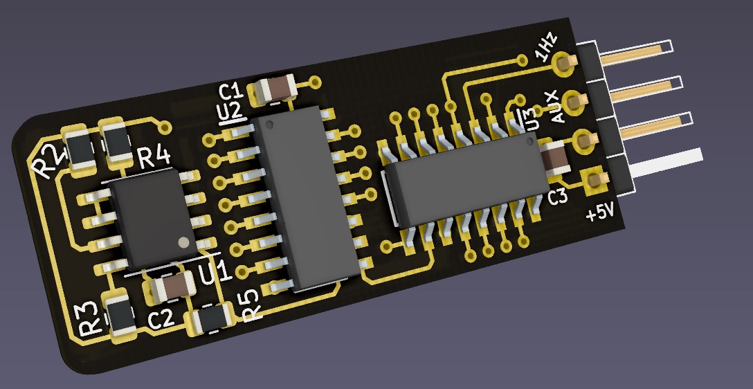
Update to the 1Hz source board
I was able to use the existing flip flop IC (74HC47). Below is a example of setting the hour time:
Stay tuned for the Rev B post where I will show all of these updates implemented on a new revision of the PCB, done in OshPark AfterDark!
Thanks for reading!