How does it work?
The circuit keep track of time, in 12 hour format, using an external 1 Hz source. The 1 Hz source comes from a 4 pin header, and allows to be changed out in the future.
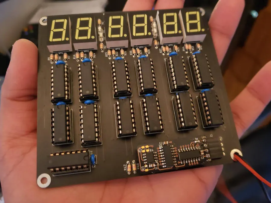
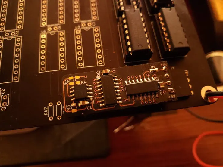
Populated PCB close up
Parts List
Display LEDs:
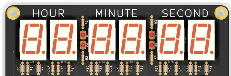
Display LEDs
For the display LEDs, I am using common anode 7 segment displays. This variant is 0.56” tall and has a red illumination color. There are 2 sets of LEDs as use the “colons” in a typical clock display.
Seconds Counter:
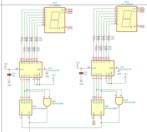
Seconds counter
The second counter comprises of 4 ICs: 74LS47 (2x), 74HC393N (1x), and 74HC08N (1x)
The 74LS47 is an active low 7 segment LCD driver. The 74HC393N is a dual 4 bit binary counter that used to count both the ONES and TENS section of the seconds part of the clock. One half of the IC counts the ONES and the other half of the TENS.
When the ONES counter reaches “1010” in binary, the AND gate resets the counter. The reason it’s using binary “1010” is because it is an active high reset. If “1001” was used, it would reset as soon as it hits 9, never actually seeing it. When it resets, it also increments the TENS counter.
When the TENS counter reaches “0110” in binary, the AND gate resets the counter. The reason it’s using binary “0110” is because it is an active high reset. If “0101” was used, it would reset as soon as it hits 5, never actually seeing it.
Since seconds and minutes both count from 0 to 59, this circuitry can be repeated for counting minutes as well.
Minute Counter:
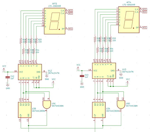
Minutes counter
As you can see, the minutes counter and seconds counter follow the same approach since they both count from 0 to 59. When the TENS portion for the second counter resets, it increments the ONES portion of the minute counter.
Hour Counter:
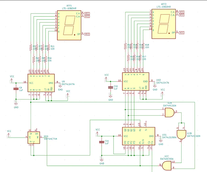
Hour counter
The hour counter was a bit tricky to figure out because I wanted to keep track of time in a 12 hour format. The requirements for counting hours in a 12 hour format (1,2,3,…11,12,1…):
- Count from 1,2,3…down to 12.
- Once 12 is about to reset, it should go back to 1.
- The ONES counter should count from 0 to 9 and then 0 to 2. Once both the TENS is at “1”, ones is at “2”, the minute is at 59
This requires a per-settable counter that can load in a fixed starting point. The 74LS190 was a perfect fit for this. It has the option to load in a fixed starting point.
The TENS counter of the hour is controlled by a D flip flop since it only has to count 0 to 1 and back to 0. The ONES counter of the hour is preset to 1. The RC (ripple count) of the ONES counter is the clock pulse for the TENS counter. When the ONES counter is 3 AND TENS counter is 1, both counters are loaded with the preset settings. This makes sure the hour count goes from 1 to 12 and then back to 1. Two NAND gates were used to make an AND gate to avoid using a separate IC for the AND gate.
Setting the Time:
No clock would be complete with out the ability to set the time. To set the time, 2 OR gates were used. One OR gate to select between the actual clock signal or an external push button. This is applied to both the minute and hour time set.
Clock Source:
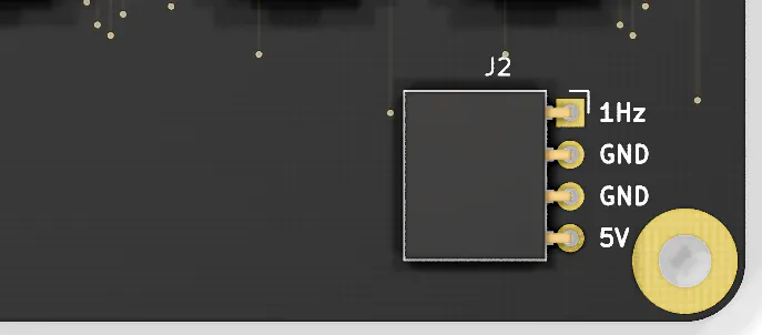
Clock Source
There is a 4 pin header (0.1” spacing) that allows plugging in different 1Hz clock source.
This is the clock source from my other post. If you decide to build the clock, you’ll also need to build this. You can also bring attach your own source as well. Make sure you get the IO correct.
Clock Source
Layout:
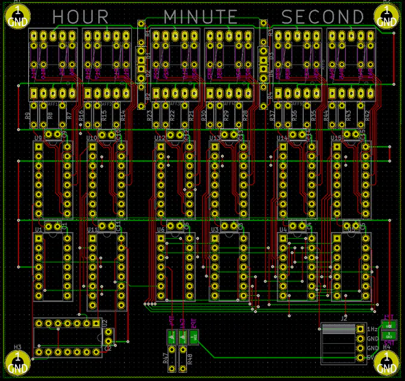
Layout
All through hole components are used and all the routing is done on 2 layers.
Building / Testing
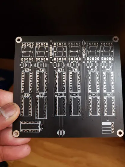
Unpopulated PCB
This whole clock uses +5V as the voltage source.
At the start of the article, I mention that I use red 7 segment LED displays. Turned out I had white 7 segment LED displays laying around so decided to use that. However, I miscalculated the current limiting resistor (I was mistakenly looking at the datasheet for the wrong part). Which is why it appears to be really bright. By the time I realized, it was too late to turn back.
The 7 segment LED display will have the required voltage drop to light it up. Using ohms law (V=I*R), the current limiting resistor can be determined. If you build it using the display on the parts list, the forward voltage (Vf) is 2V. This means you need to drop 3V across the resistor.
Vf = 2V
If = 25 mA
V = I * R
(5.0 - 2.0) = (0.025 * R)
3.0 = 0.025 * R
R = 120 ohms
Final Result
To show the effect of the clock transitioning between 12 am/pm to 1 am/pm, I connected the 1Hz clock source to the minute set button. You’ll notice that the minute goes from 1 to 3. This is result of the minute counter incrementing by the 1Hz clock source and then the “manual mode”.
The “clock dot” LEDs are blinking at the same rate as the clock source since they are connected to that said source.
Final result
Summary
There were a couple of things that did not work on the first try:
- Hour counter was not working
- Time setting was not working
Please refer to Rev B to see how fixed these two items.
Thanks for reading!