Adding Bluetooth to your next project
In this tutorial, I will be going over how to interface the HC-5 Bluetooth module to an Arduino board.
The HC-05 module is very straightforward and simple to use. It can be configured as a Primary or Secondary device. It has 6 pins for connections.
This device can be connected as a software serial port for any microprocessor. For this post, I will be use an Arduino Nano.
Primary Bluetooth Device Setup
Secondary Bluetooth Device Setup
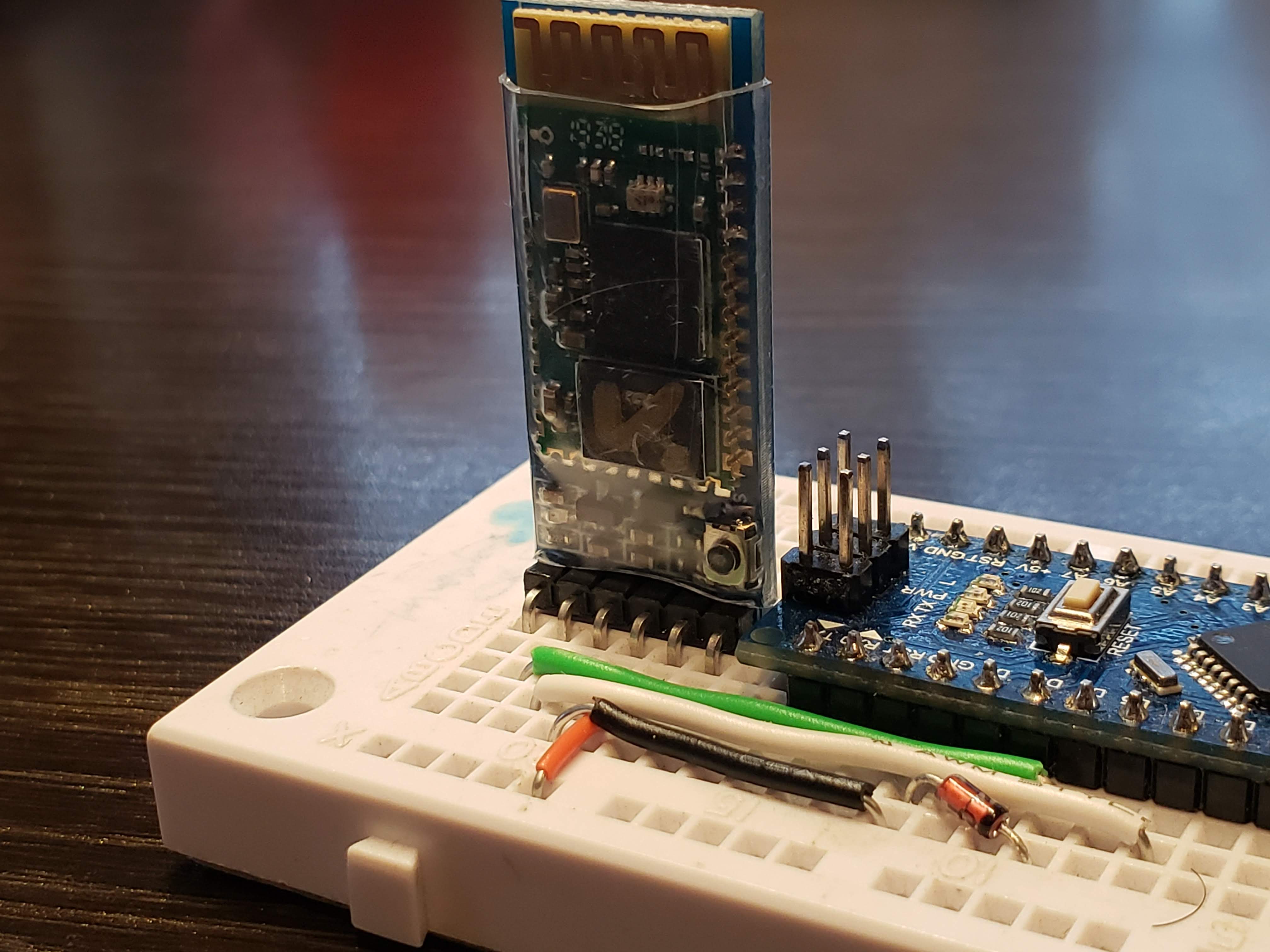
The version I bought from eBay has a pushbutton that has to be pressed during the configuration of the device.
Parts Used
| Part number | Quantity |
|---|---|
| HC-05 Bluetooth module | 2 |
| Arduino Nano | 1 |
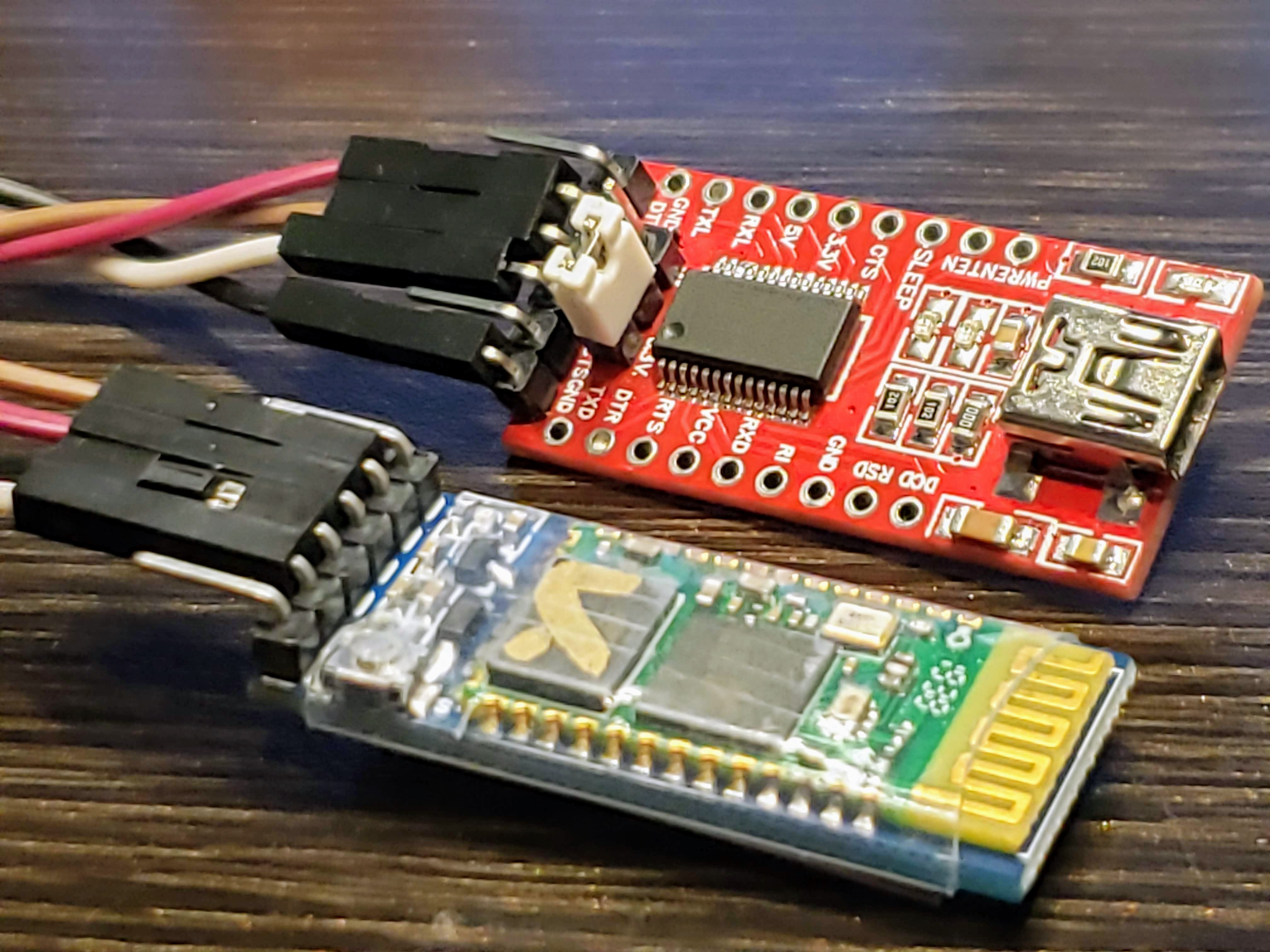
| USB to FTDI board | 1 |
| Breadboard | 1 |
| Jumper wires | 8 |
| 3.3v Zener Diode | 1 |
Here are the pinouts and connections to an Arduino nano:
Pinouts: Primary
| HC-05 | Arduino Nano |
|---|---|
| State | NC |
| Rx | 4 |
| Tx | 6 |
| GND | GND |
| Vcc | +3.3V |
| En/Key | NC |
Pinouts: Secondary
| HC-05 | FTDI USB Board |
|---|---|
| Rx | TX |
| Tx | RX |
| GND | GND |
| Vcc | VCC |
For the FTDI board, make sure the jumper is set to 3.3V
Usually, the state pin allows the control of the AT mode. AT mode is used to configure the device. For the versions with the button, the state pin doesn’t need to be connected.
Software
The Arduino code needed to talk to the HC-05 module is shown below:
#include <SoftwareSerial.h>

#define bt_tx_pin 4     // connect to hc-05 rx pin
#define bt_rx_pin 6     // connect to hc-05 tx pin
#define bt_en_pin 9     // connect to hc-05 en pin
#define bt_state_pin 10 // connect to hc-05 state pin

SoftwareSerial bt_serial(bt_rx_pin, bt_tx_pin);

void setup()
{
    pinMode(bt_rx_pin, INPUT);
    pinMode(bt_tx_pin, OUTPUT);
    pinMode(bt_en_pin, OUTPUT);
    pinMode(bt_state_pin, OUTPUT);

    Serial.begin(9600);
    bt_serial.begin(38400);
}

void loop()
{

    if (bt_serial.available())
    {
        Serial.write(bt_serial.read());
    }

    if (Serial.available())
    {
        bt_serial.write(Serial.read());
    }
}
Only a handful of AT commands are needed to configure the module as either a Primary or a Secondary. A link to all the AT commands are linked below:
In the event you encounter an error when sending an AT command, refer to this link:
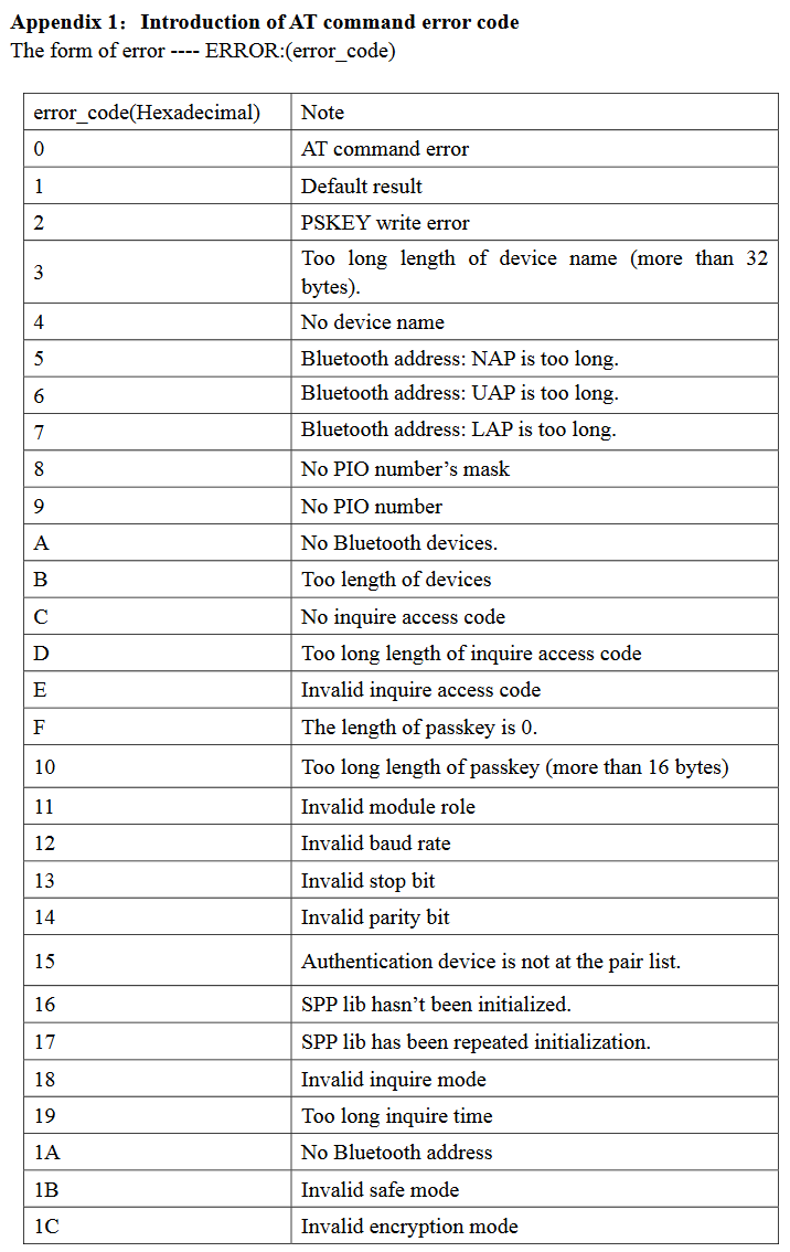
Configuration
After connecting up the module to the Arduino and loading the program, the module should be blinking rapidly.
Place in AT Mode
- Remove the GND pin connection
- Press and hold the button near the state pin
- Connect the GND pin back to the Arduino
- It should now to blinking every second
- Open up the terminal
Once you’re in the terminal, type AT and it should reponse back with OK.
Make sure that each command has a termination of
\r\n
Get device address
One device will be the Primary and the other will be the Secondary device. Use the AT+ADDR? command to find the address of each module
1st Device: Primary

>>> AT+ADDR?
+ADDR:14:1:141194
OK

2nd Device: Secondary

>>> AT+ADDR?
+ADDR:98D3:41:F5CC0B
OK
Configure Secondary Device
Open up a terminal with a Baud-rate set to 38400 and line termination "CR+LF". Hold on to the button while sending these commands
>>> AT+ORGL
OK
>>> AT+UART=38400,0,0
OK
>>> AT+RMAAD
OK
>>> AT+ROLE=0
OK
>>> AT+CMODE=0
OK
At the very end, type in AT+RESET this will initialize the device. At this point, the device should be blinking rapidly
Next we configure the Primary device
Configure Primary Device
Hold on to the button while sending these commands
>>> AT+ORGL
OK
>>> AT+UART=38400,0,0
OK
>>> AT+RMAAD
OK
>>> AT+ROLE=1
OK
>>> AT+CMODE=0
OK
>>> AT+BIND="98D3,41,F5CC0B"
OK
At the very end, type in AT+RESET this will initialize the device. After a few seconds, the two devices should pair up. This will indicated with two quick blinks every second on both Bluetooth devices.
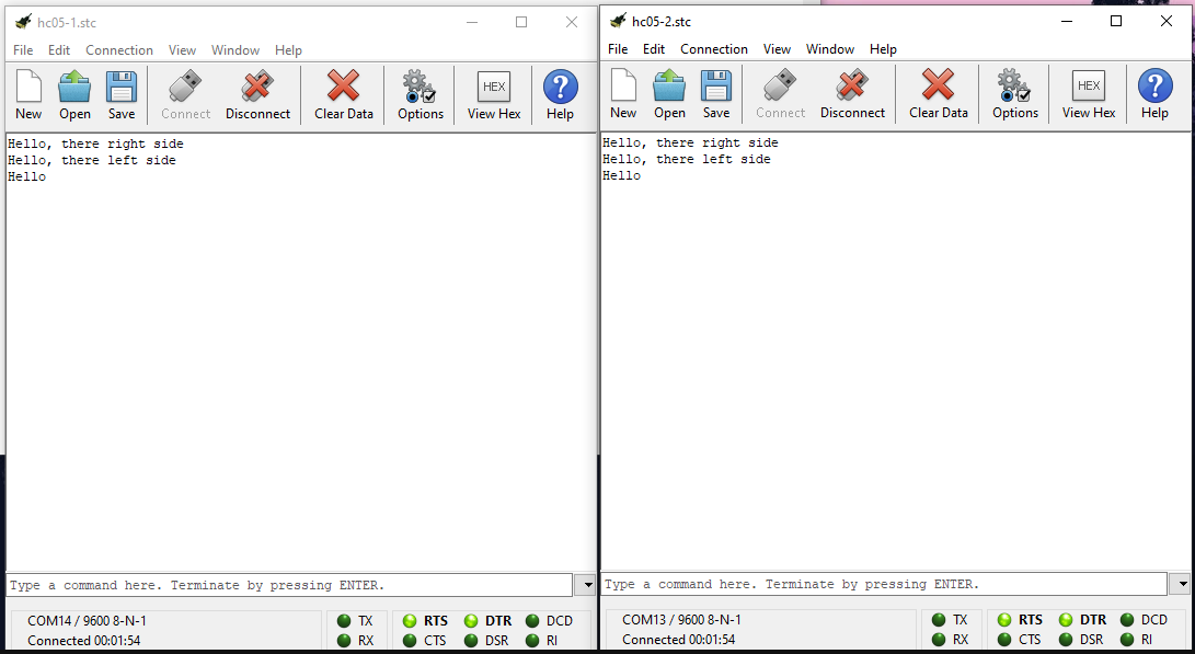
That should be it. Now you have Arduino devices that can communicate with each other over Bluetooth. On the next post, I will be showing how to build chat window using two Arduinos over Bluetooth. Stay tuned!